Four Days in May (FDIM) is an annual QRP convention that is held in Dayton, Ohio. A series of talks are usually given and for the 2022 event, there was an interesting presentation given by Hams Summers (G0UPL) about his new QDX transceiver kit.
This is a 5-watt radio for the 80m, 40m, 30m and 20m bands and is designed for digital modes like FT8. The basic kit currently retails for just $69 but there may be additional costs like import duties. It is still a very cost effective way of getting on the bands especially when you consider how many main brand radios costing $1000++ must be sitting on one frequency doing FT8 day after day.
Hans writes on his website... "QDX is suitable only for single tone FSK modes, which covers the majority of digital modes in use today. This includes everything in WSJT-X, JS8Call, some fldigi modes e.g. RTTY, Olivia and more. QDX is not suitable for on/off keyed modes such as CW because it does not have click-reducing RF envelope shaping; furthermore it is not suitable for phase shift keyed modes such as PSK31 or modes involving multiple concurrent tones such as WinLink,"
The QDX is supplied with the surface mount parts already on the PCB but some level of experience is still required to build and assemble this kit. I don't think it's for absolute beginners.
The power output versus the supply voltage is shown above. As the frequency is relatively low... 3.5 MHz to 14 MHz... the performance of the output stage is pretty good.
Hans did mention that there are plans for a similar radio covering 20m to 10m ...14 MHz to 28 MHz... and the challenge then will be to have a reasonable output at the higher frequencies.
Demand for this kit has been huge so check on the QRP Labs website for availability. There is also a lot more information about the radio on that site.
The presentation itself covers the basics of digital modes before exploring what is going on in the QDX radio.
The video of the presentation which was only put up on YouTube on the 14th of November 2022 is about an hour long but the audio level is very low. I had to use headphones to listen to it.
Back in the first half of 2022, I was following the progress of what was termed the 'ICOM SHF Project'. ICOM first announced this in December of 2021 and it suggested that they were developing a transceiver for the 2.4 GHz and 5.6 GHz microwave bands. See my earlier post HERE.
The blog post got a good deal of traffic and it was obvious that a lot of people were interested in this product even if was supposed to be for only two microwave bands.
I don't think many people had an idea earlier in the year just what ICOM had in the pipeline and it turned out to be pretty amazing.
In this post, I'll look at the new IC-905 in two parts. The first part is a summary and if anyone wants to look at the finer detail, that will be in the second half of this post further down.
In a future post, I'll look at the 10 GHz system.
Part 1 - The ICOM IC-905 in summary
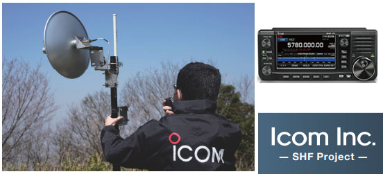
The ICOM IC-905
At the Tokyo Hamfair in August of 2022, ICOM announced their new IC-905 radio which covers the following bands... 144 MHz (2m) 432 MHz (70cms) 1296 MHz (23cms) 2.4 GHz (13cms) 5.6 GHz (6cms)
They also have an optional transverter for 10 GHz (3cms).
As you can see from the photo above, it does have a similar appearance to the current IC-705 model which covers all of the HF, 6m, 2m & 70cms bands.
Note however that there is no RF in this part of the IC-905, it's just the control unit. The radio itself or at least the RF part of it is in the head unit which goes up next to the antenna.
This is part of the concept of putting the control unit indoors where the user is and putting the radio (RF) section up at the antenna. The 'LAN Cable' connecting the two will use PoE (Power over Ethernet) which will carry power and control signals up to the RF module as well as transferring the signals from the radio back down to the controller.
The main point here is to eliminate losses from coaxial cables running from the radio shack to the antenna. These can be really high at UHF and Microwave frequencies.
Some features of the IC-905 system...
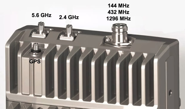
1) The power output is 10-watts on 144 MHz, 432 MHz and 1296 MHz from a single N-Type connector. There is a separate SMA type connector for 2.4 GHz and 5.6 GHz and the power on those bands is 2-watts.
2) The controller has a 4.3 inch (11cm) colour display and as you might expect, a real time spectrum scope and waterfall display.
3) All the usual analogue modes like FM, SSB & CW as well as the D-Star digital mode which is standard for an ICOM radio.
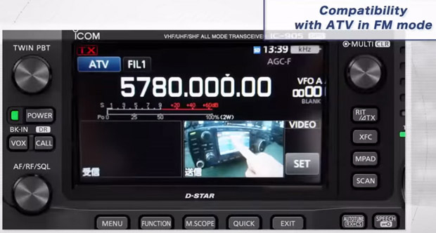
4) One nice feature is ATV (Amateur TV) in FM mode.
5) One feature of huge importance is that the RF module will be frequency locked by GPS. This is a major shortcoming in several of the existing ICOM rigs on the market in that frequency drift on some digital modes on the UHF bands is a major problem. The GPS locking should help resolve this.
Price & Availability...
As of November 2022, ICOM have not announced a price for the IC-905. I suspect it will be in the $2000-$2800 price range but we'll have to wait and see.
As for availability, they haven't announced it. I suspect it will be the second half of 2023 before we see any units for sale.
Game Changer...
When ICOM released their IC-705 radio, there was huge interest in it despite it being a low power 10-watt radio. One of the key selling points is that it was a 'shack in a box' with all of the bands from 1.8 MHz to 432 MHz in one unit.
In a similar vein, the new IC-905 is very much a 'shack in a box' for the VHF bands and above. If ICOM had announced a new VHF/UHF radio with just 144 MHz, 432 MHz & 1296 MHz, there would be a lot of interest in it. The fact the IC-905 has 2.4 GHz and 5.6 GHz as well is pretty amazing.
I suspect the biggest change will be to the 1296 MHz or 23cms band. There is a serious lack of radios available for this microwave band and getting a separate radio for just one band is prohibitive.
Close up of the base of the Diamond X6000A
I can see a LOT of people buying Tri-Band type verticals made by the like of Diamond and Comet and using them with the new IC-905. I think it's going to generate a lot of activity on the 23cms band in urban areas in many parts of the world.
The thing about a radio like this is that it is really versatile. People may come up with new ways of using it that we haven't considered at the moment.
I can really see this radio being a game changer for the UHF and low microwave bands IF the price isn't too high.
***
Part 2 - The ICOM IC-905 in more detail
IC-905 Controller... Let's have a look at this is a bit more detail.
The image above shows the front of the IC-905 and you get some idea of the depth as well.
The photo above is of the front of the controller from the Toyko Hamfair last August.
The photo above shows the rear of the controller and again, you get some idea of the depth.
As you can see from the photo above, there is very little on the rear of the controller other than two heatsinks.
While the IC-905 uses a 12-volt supply, it seems likely that there is a much higher voltage going up the Power over Ethernet cable to the RF unit. It's likely that there is some type of switch mode power supply in the controller to generate this higher voltage and a reasonable heatsink is required for that. There are of course all of the low voltage supplies to all of the electronics in the controller as well and again, a heat sink aids in keeping things cool.
The image above shows the right hand side of the controller.
The image above shows the right hand side in more detail. The port with the Green LED and the cable in it is the Power over Ethernet cable that goes to the RF module.
The image above shows the left side of the controller with the various ports.
The photo above is an actual photo of the left side of the controller.
And now onto the RF module. This image above gives an overview of the underside of the RF module. From left to right...
a) The cable on the left is Power over Ethernet LAN cable from the controller unit.
b) The BNC socket has an RF output at 10 MHz which is controlled by a GPS unit inside the RF module. The 10 MHz signal reference from here is fed to the optional 10-GHz transverter and provides that unit with a stable frequency reference.
c) The connector on the right is for the CX-10G which is the optional 10 GHz transverter.
This image above is another view of the underside of the RF module.
The image above is the top side of the RF module. All 2m, 70cms & 23cms signals are fed out via one N-type socket. Both the 2.4 GHz and 5.6 GHz bands have their own individual SMA socket. There is also a SMA socket for a small whip antenna for to receive GPS signals.
The image above gives another view of the top side of the RF module.
The image above shows the top side with the GPS antenna connected.
The image above is an actual photo of the RF module on display at the Tokyo Hamfair.
If we consider that a N-type connector is about 2cms in diameter then the dimensions of the RF module above is about 18cms across and 26cms in height. The depth is perhaps in the region of 8cms.
In terms of operation, the new IC-905 is basically the same as the popular IC-705.
This image above is a screenshot from the controller showing it operating on the 5.6 GHz band with a selection of modes.
The image above is a screenshot of the 11cm display showing a selection of menu items.
One amazing feature of this radio is it's ability to use ATV (Amateur TeleVision). In the above image, you can see a received ATV signal inset in the screen.
And this is the received signal on full screen.
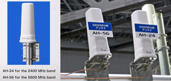
ICOM also intend to sell omni-directional antennas for both the 2.4 GHz and 5.6 GHz bands.
I suspect third party antennas for these bands will be a lot cheaper.
Video... and finally, this is the promotional video from ICOM for the IC-905
That's it. I've done my best to collate all of the information available and put it in one spot. We'll just have to wait now until ICOM announce a release date and price.
Addendum 25th Dec 2022... At a recent presentation, ICOM had this slide which showed the frequency stability of the new IC-905 versus the old IC-9700.
The IC-9700 which was released in 2019 and is a VHF/UHF transceiver covering 2m, 70cms and 23cms. It is not frequency disciplined by an external source and as can be seen from the chart on the left, it can drift hundreds of Hz with a change in temperature on the 23cms band.
This isn't an issue on say FM, D-Star, SSB or CW but it is on the very weak signal modes like FT8 or WSPR where a high level of frequency stability is required. This has led to some third party providers providing frequency stability solutions.
The chart on the right by contrast is that of the IC-905 at roughly four times the RF frequency. The IC-905 which is frequency stabilised by GPS only drifts a few Hz with changes in temperature.
This really is a game changer for all the VHF, UHF and SHF bands as frequency stability is now essential for very weal signal modes.
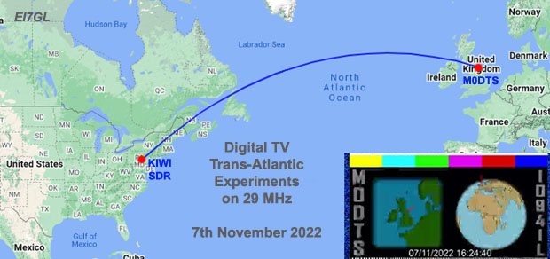
On the 7th of November 2022, Rob M0DTS managed to send a TV signal on 29.250 MHz across the North Atlantic!
First off, some information. The map above shows the path... M0DTS is located in the NE of England and he was using an online Kiwi Software Defined Radio (SDR) which was located in the state of Pennsylvania.
Rob was transmitting his Digital Amateur TV signal on 29.250 MHz using 100-watts into a 3-element Yagi. The Kiwi SDR in the USA was using a simple loop antenna for reception of the signals. As the SDR was online, Rob was able to log in and see if his DATV transmissions were being received.
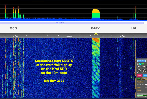
The initial tests were done on the 6th of November as can be seen from the screen capture above.
On the left are the SSB signals the Kiwi SDR was receiving down around 28.5 MHz. On the right, you can see some FM signals up around 29.6 MHz. Rob's DATV signal can be clearly seen at 29.250 MHz.
M0DTS writes... "Been watching my 29.250MHz DATV test signal on a kiwisdr in Pennsylvania... there is hope! This was 66Ks DVB-S2, Lots of frequency fading but on peaks maybe it will just work in DVB-S2... I can also do DVB-T, but today was just gauging signal strengths."
There's a lot of information in that waterfall display if we examine it closely. First off, left to right is frequency and up and down is time.
The path for this experiment was about 5,500 kms in length and probably involved two hops off the F2 layer in the ionosphere. Sometimes the signals arrive in phase and appear strong, sometimes the signals are out of phase and cancel each other out.
As the DATV signal is spread out over 80 kHz, the higher frequency part of the DATV signal has a slightly shorter wavelength than the lower frequency and longer wavelength part.
What's fascinating is that you can see in the DATV waveform where the signal is being cancelled out. It starts at the higher frequency and as the conditions change over time, the 'notch' moves lower in frequency as the longer wavelength signals cancel out.
As you might imagine, losing big chunks of the digital video signal plays havoc with reception.
Back in the 'old days'.. say the 1970's and 1980's, there were times during the peak of the sunspot cycle when broadcast TV signals around 45-55 MHz were seen around the world. At the time of course, it was analogue TV but the F2 signals were noted for being highly distorted as different parts of the signal were missing.
Anyway, I digress :o)
On the 7th of November, Rob managed to successfully send an amateur TV signal across the Atlantic when the signals were stronger.
M0DTS writes..."Today's quick 10m test across the pond. Txing 18Ks DVB-S 2/3 -> receiving IQ signal output from kiwisdr into sdrangel then demodulated, note the kiwisdr has 20KHz bandwidth limitation. So DVB-S is possible over HF path when fading allows :-) "
In conclusion: On the face of it, sending a signal across the North Atlantic on the 10m band is no big deal. It has been done countless times on CW, SSB, FT8, FM, etc.
It's not the same as say Slow Scan TV (SSTV) where a single image is sent over SSB. What makes this significant is that it's actual video.
The amateur TV community have been experimenting for the last few years trying to compress television signals into smaller and smaller bandwidths. In the UK, they're been doing this at 71 MHz, at 146 MHz and the higher amateur radio bands.
With the improving conditions on the HF bands, experiments like this are now a possibility on bands like 29 MHz and perhaps in time at 51 MHz as the sunspot cycle improves.
Just a quick post. As a storm passed over Ireland this afternoon, I dropped my vertical antenna for 28 MHz to protect it from the high winds. Normally the half-wave vertical sits about 4.5 metres above ground level and is reasonably clear in most directions.
I noticed that while it was lying horizontal on the ground, I was still receiving WSPR signals on 28 MHz!
I propped up the antenna so that it was lying horizontal and about 30cms above the ground. After 4-hours of listening, I heard 52 stations on WSPR on 28 MHz and these are shown above.
It's just surprising to see signals coming in from North America on 28 MHz on an antenna that almost on the ground and I literally have to step over.
Just a quick post to say that there was a F2 layer opening between Europe and North America on the 40 MHz band on Friday 4th Nov 2022.
With the improving solar conditions, North-South paths on 40 MHz or even 50 MHz are no big deal, it's the East-West paths that are more difficult and require conditions to be very good.
An East-West opening via the F2 layer at 40 MHz doesn't mean that an East-West opening at 50 MHz is imminent but it does show that things are heading in the right direction.
This is why experiments and beacons on the 40 MHz band are so important, they act as an early warning system for higher bands like 6m
Every day, I leave my HF radio on the 28.1246 MHz to listen for WSPR signals. My PC then decodes these and sends the reception reports up to WSPRNet website for others to see.
The QRSS (very slow morse code) band is just a few hundred Hz below the 10m WSPR band and I noticed in the WSPR waterfall that two QRSS signals were present so I had a look.
The image above shows the QRSS signals that I was hearing over a period of about 20-25 minutes on the 1st of November 2022.
VE1VDM in Canada and G0PKT in the east of England had reasonable signals and they were the two I had noticed initially. G6GN in England is also present but quite weak. There are other very weak QRSS signals as well but I was unable to ID these.
The locations of the relevant stations are shown on the map below.
VE1VDM in Nova Scotia is 4000kms from my location and is easily explained as it's an ideal one F2 layer hop away on 28 MHz.
The signals from G6GN at 400kms and G0PKT at 650 kms are not so easily explained. If it was the Summer months then we might think it was Sporadic-E but, this was the first of November AND G0PKT is pretty much there all of the time every day when the band is open.
I suspect that I am receiving these signals via F2 layer backscatter. In the past (pre digital days), backscatter signals were pretty much buried in the noise with the SSB and CW modes. Now however, WSPR has no problem decoding signals that are 20dB below the noise level and I can see QRSS signals which are in the region of -15 to -20dB.
I think a lot of those 'close in' signals that we are now seeing on WSPR or FT8 on 28 MHz are in reality via backscatter.
You can see from the map above all of the WSPR stations I heard on 28 MHz on the 1st of November. Meteor Scatter? Forward scatter via Sporadic-E? I'm opting for F2 layer backscatter.
I'm using an omni-directional vertical on 28 MHz so I can't beam headings. Maybe someone else wants to do some tests? See which direction those 'close in' signals are strongest. The direct path OR beaming in some other direction at a potential back-scatter point?
Irish public libraries provide all users with a wide range of free online services including eBooks, eAudiobooks, eMagazines, online courses and online newspapers.
Many books and periodicals on radio-related topics are available. Of particular interest to radio operators are the availibilty of the copies of "CQ Amateur Radio" and "Practical Wireless" via the Libby platform.
Registration with www.library.ie is free of charge, but subject to a visit to any of the public libraries to confirm the registration.
While this post applies to radio amateurs and other radio enthusiasts in Ireland, it is worth checking your local public library to see if they offer a similar service.
I read this morning the sad news that Richard Brunton, G4TUT from Rayleigh, Essex, England, passed away. He was 77.
Richard was the editor of the popular Southgate Amateur Radio News website which is now offline.
The site had a daily digest of amateur radio news items with some space news thrown in the mix as well. It must have taken a huge amount of time to trawl various websites and collate all of that information on a daily basis.
I often noticed that the Southgate ARC news items was then in turn the source of news for many other amateur radio sites.
EIRSAT-1 stands for the Educational Irish Research Satellite 1. It is a satellite about the size of a shoe box, called a CubeSat. It is a small-scale satellite but still needs the same functionality as a large mission.
The satellite must be able to power itself, orientate itself in space, communicate to the ground station being built on the roof of the UCD School of Physics and collect data from the three science experiments on-board.
EIRSAT-1 in the lab
The first experiment is a novel gamma-ray detector, GMOD, which is being developed in UCD. GMOD will detect gamma-rays from both cosmic and atmospheric phenomena.
The second experiment, EMOD, consists of a payload developed with Irish company, ENBIO Ltd., to monitor the in-flight performance of their thermal spacecraft treatments, SolarWhite and SolarBlack.
The third experiment, Wave Based Control (WBC), is a novel attitude control algorithm, developed in the UCD School of Mechanical and Materials Engineering, which will be tested for the first time in space on EIRSAT-1.
In February 2022, the payloads, GMOD and EMOD, and the antenna deployment module were qualified for space flight. In the last year, the payloads have been subject to environmental testing at the ESA CubeSat Support Facilities in Belgium.
During the lockdown and Covid-19 restrictions, the team has been operating the satellite remotely. The satellite hardware must be kept in a ISO Level 8 cleanroom in a lab in the UCD School of Physics. Hairnets, gloves and anti-static coats have to be worn to prevent dust and contaminants landing on the satellite components.
A private YouTube stream is used to monitor the hardware in the cleanroom and Discord is used for operators to converse during satellite testing and share screens to see the outputs of the on-board computer.
Hopefully all going well a launch date for next year (2023) is a go.
I have been talking to the team in UCD, and they would love to get feedback from radio amateurs on signals reports from the new satellite after its launch's next year.
They will provide the frequencies after launch.
I wish them the best of luck and look forward to giving signal reports.
Lez, EI4GEB
Some RF info...
On-board Communications: The on-board CMC (Common Mode Current) transceiver is the space-qualified CPUT VUTRX transceiver supplied by ClydeSpace. The communications system uses UHF downlink (430-440 MHz) and VHF uplink (140-150 MHz) bands. The transceiver provides 9600 baud downlink and 1200 baud uplink, and implements a GMSK downlink and AFSK uplink configuration. The AX.25 protocol is used for uplink packets, while a CCSDS convolutional encoder may be used for downlink.
ADM (Antenna Deployment Module): EIRSAT-1 will use a custom ADM designed and built at UCD which will be mounted on the -Z end of the satellite deploys two dipole antennas, one for UHF downlink and one for VHF uplink. Both dipoles are composed of two tape spring antenna elements, deployed from opposite sides of the module, as seen in many previous and COTS antenna designs. The elements are 5 mm wide, made from a Copper Beryllium alloy and attached to spring loaded doors at each side of the module. They are coiled inside the ADM before deployment, within the 7 x 100 x 100 mm overall dimensions of the module. When EIRSAT-1 is clear of the CubeSat deployer the ADM will activate a burn wire release mechanism allowing the module doors to open and the elements to uncoil into their operational positions and stay in that configuration for the remainder of the mission.
From the IRTS News - 16th Oct 2022... Jeremy Boot G4NJH reports on Amateur Radio Newsline that the team developing EIRSAT-1 has returned from Belgium, where the project underwent rigorous testing at the CubeSat Support Facility, including an assessment to ensure it would survive launch. The University College Dublin team includes David Murphy, EI9HWB, and Lána Salmon, EI9HXB. They are developing the low-earth-orbit CubeSat as part of the European Space Agency's "Fly Your Satellite" programme. ESA administrators have said in the past that they view the project as a way to grow a new generation of space scientists and engineers to nurture a space programme for Ireland. The satellite is tentatively scheduled for a launch from an ESA base in French Guiana by early 2023. The Project's website is at www.eirsat1.ie .
It's been about five months since I last posted on the blog as I've taken a break from the radio scene.
I've had my radio listening away on WSPR on 28 MHz all of the time but truth be told, I often didn't even check what was heard. The reception reports just got uploaded automatically by the PC to WSPRNet for others to see.
It's amazing once you go 'outside the radio bubble', it can take quite a while to get back in and catch up on all the things that happened.
I'm gradually working my way through the backlog of radio related emails and material and I hope to start posting again on a more regular basis.
In 2021, ICOM announced that they were developing a transceiver for the microwave bands. At the time, it seemed like a highly unusual but welcome development.
See the Addendum at the bottom of the post for updates...
In April of 2022, they announced more details. They write... "Under the theme of “ICOM SHF Project – Super High Frequency Band Challenge –”, we started to develop a new amateur radio available for use in the 2.4 GHz and 5.6 GHz bands.
Icom engineers are working hard to research and develop a number of never cleared challenges within the SHF band, such as large cable loss and higher frequency stability requirements. The ultimate goal is to bring it to the market as a new radio product. Icom is striving to bring to you a new era in fun and possibilities of an SHF band amateur radio, which to date has had high technical and equipment hurdles to overcome, and we hope to make these bands more attractive and active so that anyone can easily operate on them. We are developing an epoch-making SHF band amateur radio that no one has never imagined before."
The microwave radio is essentially a box that this designed to be fitted at the top of a mast or roof of a house. This will keep any coax losses to an absolute minimum.
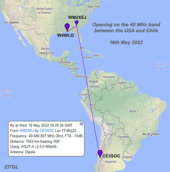
There was an interesting opening on the 18th of May 2022 when the FT8 signals from the US experimental 40 MHz station WM2XEJ in Georgia were heard by CE3SOC in Chile.
With the solar flux on the increase and more openings on the higher 50 MHz band, it's probably not such a great surprise that there was an opening between North and South America at 40 MHz.
It is however nice to see more interest in the band from amateur radios stations in South America and hopefully we'll see many more reports.