On Sunday the 18th of December 2022, ICOM Japan held their own exhibition at their Narayama Research Institute to display some of their new projects. This included the upcoming IC-905 transceiver which will cover 144 MHz, 432 MHz, 1296 MHz, 2.4 GHz & 5.6 GHz. They also have an optional 2.4 GHz to 10 GHz transverter.
I won't go into the full details of the radio here but you can read about it in my previous post HERE
The big question is what is the price going to be and when will it be released? In my earlier post, I guessed that it might be in the $2000 to $2800 price range.
HAMLIFE . JP reports on Twitter from the exhibition that the guide price for the IC-905 will be 400,000 Yen. This is around $2930 or €2760.
The optional 10 GHz transverter will be 150,000 Yen which is about $1100 or €1040.
The release date is expected to be the Spring of 2023 which is a bit earlier than I was expecting.
Now the unknowns are... Will it be too expensive??? What will the demand be like??? Will the demand be different in the various markets... Japan / North America / Europe / Australia ???
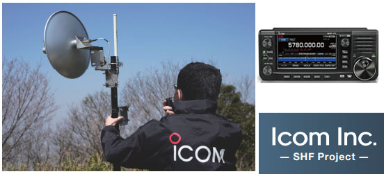
On the 17th of November 2022, ICOM staff in Japan conducted some experiments over a 25km obstructed path on the 5.6 GHz and 10 GHz microwave bands with the company's new IC-905 transceiver.
The photo above shows the view from the roof top of the six story building at ICOM's headquarters in Osaka. The two parabolic dishes for 5.6 GHz and 10 GHz are beaming towards the Ikoma mountains. The RF module of the IC-905 and the 2.4 GHz to 10 GHz transverter are also shown. The station at ICOM HQ was JK3AZL.
The second portable station JL3ZAB with a similar setup was operating from a hill near Kizugawa City which was about 25kms away on the other side of the Ikoma mountains. The map below below shows the path in Blue. The important point here is that both stations were blocked from each other by the mountains but both were line of sight to Mt Ikoma.
Both stations started early in the morning, setting up their radio equipment and antenna systems. By 9am, both stations were able to easily catch each other's signals by pointing their parabolic antennas at the summit of Mt Ikoma using a map and compass and were able to communicate by voice on both the 5.6 GHz and 10 GHz bands.
It is believed that the propagation mode was knife-edge diffraction from the mountain peaks.
The power of the IC-905 is 2-watts at 5.6 GHz while the output power of the 10 GHz transverter is 1-watt.
The test was repeated later with JL3ZAB now operating from the ICOM Narayama Laboratory. From this lower location, the summit of Mt. Ikoma was now longer visible. They were barely able to communicate on 5.6 GHz with CW while communication at 10 GHz was not successful.
The path from ICOM HQ to their Narayama Lab is shown above in Red. The path profile is shown below albeit with an exaggerated vertical scale.
The ICOM team concluded... "It is known that in the SHF band or even higher frequencies, radio propagation gradually becomes more linear, similar to light. The Icom team thought it would be interesting to see whether communication will be impossible under non-line-of-sight conditions as in this case, or whether communication by mountain diffraction (Knife-edge effect), known as anomalous propagation, would be possible.
The experiment revealed that mountain diffraction phenomena occur even on mountains with relatively gentle peaks such as the Ikoma Mountains. Conversely, if the peaks are not visible, communication is difficult."
Analysis... Once the ICOM IC-905 goes on sale, people that purchase it may well expect only line of sight contacts as that will be the mantra of most websites and commentators. With high gain antennas and weak signal modes, there will be many unusual paths like the example above.
In an urban environment, there may well be many reflections off objects like high buildings, water towers, masts, etc.
If you consider that tropospheric ducting often occurs more often at microwave frequencies then there are bound to be surprises for those who are interested in experimenting on these amateur bands above 1 GHz.
Back in the first half of 2022, I was following the progress of what was termed the 'ICOM SHF Project'. ICOM first announced this in December of 2021 and it suggested that they were developing a transceiver for the 2.4 GHz and 5.6 GHz microwave bands. See my earlier post HERE.
The blog post got a good deal of traffic and it was obvious that a lot of people were interested in this product even if was supposed to be for only two microwave bands.
I don't think many people had an idea earlier in the year just what ICOM had in the pipeline and it turned out to be pretty amazing.
In this post, I'll look at the new IC-905 in two parts. The first part is a summary and if anyone wants to look at the finer detail, that will be in the second half of this post further down.
In a future post, I'll look at the 10 GHz system.
Part 1 - The ICOM IC-905 in summary
The ICOM IC-905
At the Tokyo Hamfair in August of 2022, ICOM announced their new IC-905 radio which covers the following bands... 144 MHz (2m) 432 MHz (70cms) 1296 MHz (23cms) 2.4 GHz (13cms) 5.6 GHz (6cms)
They also have an optional transverter for 10 GHz (3cms).
As you can see from the photo above, it does have a similar appearance to the current IC-705 model which covers all of the HF, 6m, 2m & 70cms bands.
Note however that there is no RF in this part of the IC-905, it's just the control unit. The radio itself or at least the RF part of it is in the head unit which goes up next to the antenna.
This is part of the concept of putting the control unit indoors where the user is and putting the radio (RF) section up at the antenna. The 'LAN Cable' connecting the two will use PoE (Power over Ethernet) which will carry power and control signals up to the RF module as well as transferring the signals from the radio back down to the controller.
The main point here is to eliminate losses from coaxial cables running from the radio shack to the antenna. These can be really high at UHF and Microwave frequencies.
Some features of the IC-905 system...
1) The power output is 10-watts on 144 MHz, 432 MHz and 1296 MHz from a single N-Type connector. There is a separate SMA type connector for 2.4 GHz and 5.6 GHz and the power on those bands is 2-watts.
2) The controller has a 4.3 inch (11cm) colour display and as you might expect, a real time spectrum scope and waterfall display.
3) All the usual analogue modes like FM, SSB & CW as well as the D-Star digital mode which is standard for an ICOM radio.
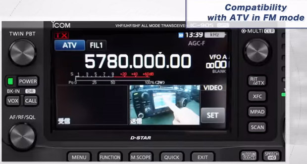
4) One nice feature is ATV (Amateur TV) in FM mode.
5) One feature of huge importance is that the RF module will be frequency locked by GPS. This is a major shortcoming in several of the existing ICOM rigs on the market in that frequency drift on some digital modes on the UHF bands is a major problem. The GPS locking should help resolve this.
Price & Availability...
As of November 2022, ICOM have not announced a price for the IC-905. I suspect it will be in the $2000-$2800 price range but we'll have to wait and see.
As for availability, they haven't announced it. I suspect it will be the second half of 2023 before we see any units for sale.
Game Changer...
When ICOM released their IC-705 radio, there was huge interest in it despite it being a low power 10-watt radio. One of the key selling points is that it was a 'shack in a box' with all of the bands from 1.8 MHz to 432 MHz in one unit.
In a similar vein, the new IC-905 is very much a 'shack in a box' for the VHF bands and above. If ICOM had announced a new VHF/UHF radio with just 144 MHz, 432 MHz & 1296 MHz, there would be a lot of interest in it. The fact the IC-905 has 2.4 GHz and 5.6 GHz as well is pretty amazing.
I suspect the biggest change will be to the 1296 MHz or 23cms band. There is a serious lack of radios available for this microwave band and getting a separate radio for just one band is prohibitive.
Close up of the base of the Diamond X6000A
I can see a LOT of people buying Tri-Band type verticals made by the like of Diamond and Comet and using them with the new IC-905. I think it's going to generate a lot of activity on the 23cms band in urban areas in many parts of the world.
The thing about a radio like this is that it is really versatile. People may come up with new ways of using it that we haven't considered at the moment.
I can really see this radio being a game changer for the UHF and low microwave bands IF the price isn't too high.
***
Part 2 - The ICOM IC-905 in more detail
IC-905 Controller... Let's have a look at this is a bit more detail.
The image above shows the front of the IC-905 and you get some idea of the depth as well.
The photo above is of the front of the controller from the Toyko Hamfair last August.
The photo above shows the rear of the controller and again, you get some idea of the depth.
As you can see from the photo above, there is very little on the rear of the controller other than two heatsinks.
While the IC-905 uses a 12-volt supply, it seems likely that there is a much higher voltage going up the Power over Ethernet cable to the RF unit. It's likely that there is some type of switch mode power supply in the controller to generate this higher voltage and a reasonable heatsink is required for that. There are of course all of the low voltage supplies to all of the electronics in the controller as well and again, a heat sink aids in keeping things cool.
The image above shows the right hand side of the controller.
The image above shows the right hand side in more detail. The port with the Green LED and the cable in it is the Power over Ethernet cable that goes to the RF module.
The image above shows the left side of the controller with the various ports.
The photo above is an actual photo of the left side of the controller.
And now onto the RF module. This image above gives an overview of the underside of the RF module. From left to right...
a) The cable on the left is Power over Ethernet LAN cable from the controller unit.
b) The BNC socket has an RF output at 10 MHz which is controlled by a GPS unit inside the RF module. The 10 MHz signal reference from here is fed to the optional 10-GHz transverter and provides that unit with a stable frequency reference.
c) The connector on the right is for the CX-10G which is the optional 10 GHz transverter.
This image above is another view of the underside of the RF module.
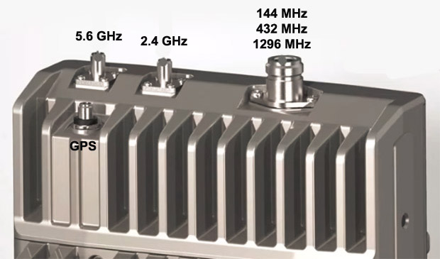
The image above is the top side of the RF module. All 2m, 70cms & 23cms signals are fed out via one N-type socket. Both the 2.4 GHz and 5.6 GHz bands have their own individual SMA socket. There is also a SMA socket for a small whip antenna for to receive GPS signals.
The image above gives another view of the top side of the RF module.
The image above shows the top side with the GPS antenna connected.
The image above is an actual photo of the RF module on display at the Tokyo Hamfair.
If we consider that a N-type connector is about 2cms in diameter then the dimensions of the RF module above is about 18cms across and 26cms in height. The depth is perhaps in the region of 8cms.
In terms of operation, the new IC-905 is basically the same as the popular IC-705.
This image above is a screenshot from the controller showing it operating on the 5.6 GHz band with a selection of modes.
The image above is a screenshot of the 11cm display showing a selection of menu items.
One amazing feature of this radio is it's ability to use ATV (Amateur TeleVision). In the above image, you can see a received ATV signal inset in the screen.
And this is the received signal on full screen.
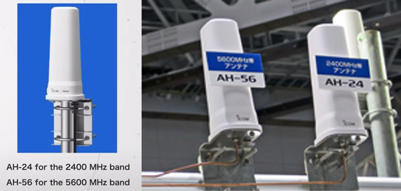
ICOM also intend to sell omni-directional antennas for both the 2.4 GHz and 5.6 GHz bands.
I suspect third party antennas for these bands will be a lot cheaper.
Video... and finally, this is the promotional video from ICOM for the IC-905
That's it. I've done my best to collate all of the information available and put it in one spot. We'll just have to wait now until ICOM announce a release date and price.
Addendum 25th Dec 2022... At a recent presentation, ICOM had this slide which showed the frequency stability of the new IC-905 versus the old IC-9700.
The IC-9700 which was released in 2019 and is a VHF/UHF transceiver covering 2m, 70cms and 23cms. It is not frequency disciplined by an external source and as can be seen from the chart on the left, it can drift hundreds of Hz with a change in temperature on the 23cms band.
This isn't an issue on say FM, D-Star, SSB or CW but it is on the very weak signal modes like FT8 or WSPR where a high level of frequency stability is required. This has led to some third party providers providing frequency stability solutions.
The chart on the right by contrast is that of the IC-905 at roughly four times the RF frequency. The IC-905 which is frequency stabilised by GPS only drifts a few Hz with changes in temperature.
This really is a game changer for all the VHF, UHF and SHF bands as frequency stability is now essential for very weal signal modes.