The management team of the Summits on the Air (SOTA) programme have just announced their new SOTA Challenge for 2026 and it's for operating SSB & CW on the 2m and 70cms bands.
Their last challenge was for the year 2024 and that was for the 28 MHz (10m) band. See previous post HERE.
SOTA is a very popular awards programme and it most of the activity on the HF bands. Any SOTA activity on the VHF bands tends to be on FM on 145 MHz so it would be nice to see more activity on SSB & CW on 144 MHz & 432 MHz.
Here is an excerpt from the SOTA posting...
2m/70cm SSB/CW
Many activators and chasers will have access to equipment already for these bands and modes - whether the old faithful FT-817 and FT-857s or newer options like the 2m option for the KX3, the timely CW modification to the cheap and cheerful Quansheng handhelds or the ubiquitous 2m transverter kits available on various auction sites for relatively low cost.
Many antenna options are available, whether lightweight Yagis, Hentennas, Oblongs, Quads, Flowerpots or J-poles (Slim or otherwise). Many propagation modes are available.
This should provide an interesting and challenging year for each individual participating, where the activators and chasers will have their work cut out to make QSOs under different conditions and via different means.
Scoring format: - Given that SSB and CW are considered useful as DX modes on these bands, points will be awarded based on distance, number of summits activated and unique callsigns logged in an activation.
Activators: - Your score will be 1pt/km for each QSO with a unique callsign (per summit) activated within the year, multiplied by the number of unique summits activated.
Chasers: Your score will be 1pt/km for each QSO with a unique callsign (per summit) chased within the year, multiplied by the number of unique summits chased.
Dates: 1 January 0000 UTC to 31 December 2359 UTC 2026
***
Over the last few years, there has been an exodus from modes like SSB and CW to data modes like FT8. Hopefully this programme will encourage people to check the SSB portions of the VHF bands more often.
If there is any activity near you then give them a call as they may need to make a certain number of contacts for it to be a valid activation of a summit.
Back on the 8th of April 2024, I reported on the very first Trans-Equatorial Propagation (TEP) opening on the 144 MHz band from UAE to Reunion Island in the Indian Ocean. Since then, this has been pretty much a daily occurence and I have been keep a record of the openings.
On the 23rd of April 2024, A65BR in the United Arab Emirates (UAE) reports that his 432 MHz signal was heard in Reunion by FR4OO via TEP. The distance was in the region of 5160kms.
Reports of TEP openings on the 70cms are incredibly rare and it's really interesting to hear about this new report. In this case, it was only a reception report but it shows the potential of the path at 432 MHz.
The composite image above shows reception of the Q65 signal at -17dB as heard by FR4OO.
TEP at 144 MHz is common enough for stations in the right location but stations using 432 MHz are really pushing the limits at what's possible. There are many different propagation modes on 70cms but surely one that allows 432 MHz signals to propagated by the ionosphere must be one of the more unusual ones.
It would be good to see more stations experimenting with TEP at 432 MHz and seeing what it possible.
Link... 1) For more examples of long distance openings on the 70cms band, see my 432 MHz page.
432 MHz TEP: In a previous post, I reported on how a signal on the 432 MHz band from Brett, PJ2BR on the island of Curacao was received by Javi, LU5FF in Argentina. The propagation mode was Trans-Equatorial Propagation (TEP) and the distance was 4853kms.
After it, there was some question about if it was real? Was it a false decode of the Q65 signal? Was there an issue with the software when changing bands from 144 MHz to 432 MHz? Reports of TEP signals on the 432 MHz band are extremely rare and people are right to be cautious.
Now we have a second example of a 432 MHz opening on the 24th of February 2023. This time, we have decodes of signals on both ends as well as visual evidence of a signal in the waterfall display as well as reception of a signal that could be heard.
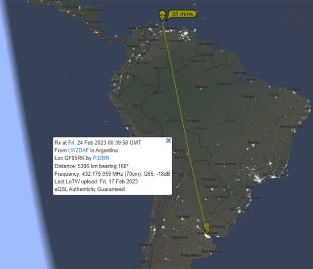
24th February 2023: Both Brett, PJ2BR and Diego, LW2DAF report that there was a TEP opening on the 432 MHz band on the 24th of Feb 2023. The time was around 00:40 UTC which was about 8-9pm local time on the 23rd of Feb for the parties involved which is around the peak time for evening TEP openings.
On this occasion, there were decodes at both ends and the distance was around 5310kms.
I have some images below so that we have a record of this opening.
The image above is a screenshot from the PSK Reporter website showing the 432 MHz path reported on the site.
This image above is from a screenshot from PJ2BR and shows the left hand side of the WSJT-X software showing reception of LW2DAF with a signal of -18dB. You can see the mode used was Q65-30B. Note that I edited the image to make it smaller vertically to remove the blank area.
This image above is the right hand side of the screenshot. It shows the reception of LW2DAF at -18dB and then PJ2BR sending the report.
Now from Argentina. This image above shows a very weak signal in the waterfall at around 700 Hz.
This image above shows LW2DAF decoding the signal from PJ2BR with a peak of -12dB. This is significant because it was now at a level where the signal might be heard.
Diego, LW2DAF said that he saw and heard the signal on 432 MHz.
This video clip above from LW2DAF on Twitter shows the reception of the signal.
This screenshot from the video shows the Kenwood radio used by LW2DAF on 432.174 MHz.
Equipment: For this TEP test, PJ2BR was using a Kenwood TS2000 with 100-watts from a Mirage amplifier.
The antenna was shown above was a M2 22-element horizontal Yagi.
LW2DAF was using 50-watts into a horizontally polarised 18-element LFA Yagi about 21m above ground level.
Analysis: As Deigo LW2DAF noted, a visual and audible TEP signal on the 432 MHz band has now been verified. It would seem that it is now only a matter of time before someone from Argentina or Brazil completes a 432 MHz contact with someone in the Caribbean using Trans-Equatorial Propagation.
From my understanding of TEP, it's Class II as shown above as an effective duct appears on the Geomagnetic Equator.
At 432 MHz, location, distance and being at right angles to the Geomagnetic Equator are even more important than they are at 432 MHz. As Diego notes, more stations on 432 MHz are needed to try this path at 70cms. It just needs two stations to be in an optimum location and for the conditions to be right.
Link: For other examples of long distance openings on the 70cms band, see my 432 MHz page.
Brett, PJ2BR in Curacao in the Caribbean reports that on the 5th of February 2023 (01:18 UTC), his 432 MHz signal were heard by Javi, LU5FF in Argentina by Trans-Equatorial Propagation (TEP). The distance was 4853 kms!
This really is ground breaking news (*). It was only on the 4th of February that I put up a post about what was up to then the only 432 MHz reception report via TEP in South America and that was from 1978. I tagged PJ2BR on Twitter about the post and a few hours later, we have a second 70cms TEP report!
The Green exchange is for 144 MHz while the Yellow is for 432 MHz (*).
Proof of Concept (*)... For this TEP opening on 432 MHz, PJ2BR was using the Q65b weak signal mode. This is significant because it means that modern digital weak signal modes can be used for TEP openings at 70cms. It's not a case of there being too much doppler or spreading of the signal that only CW can be used. This would likely require a much stronger signal for a contact to be made.
For the record, here is a screen grab off the PSK Reporter website before it disappears.
Let's hope that this news will encourage more stations in the Caribbean and in South America to try to make a TEP contact on the 432 MHz.
(*) = Caveat... Someone raised the question if the reports on 432 MHz are genuine? They do after all follow some Q65 reports on 144 MHz and they wonder if it's the software generating these 70cms reports?
It's a bit like conducting a science experiment and we have one data point, not exactly the five-sigma required for a definitive conclusion. What we need are more stations in South America and the Caribbean to test the TEP path on 432 MHz. If there are no more reception reports then it raises some question mark over this new report. If there are more reports then it means this report was probably ok.
Addendum:6th February 2023... There was another TEP 'reception report' on 432 MHz on the 6th of February 2023. This time it was from WP4KJJ in Puerto Rico to LU9FVS in Argentina.
I believe the stations involved have concerns about the software generating incorrect reports after the band has been changed.
I suspect what is required is the reception of a good old fashioned CW signal to eliminate any software issues.
While openings via TEP (Trans-Equatorial Propagation) on the 144 MHz band seem to be relatively common in South America, it's a different story on the higher frequencies.
While there have been verified TEP openings at 432 MHz in Africa in the past, any reports of TEP openings on the 70cms band seem to be extremely rare.
Back on the 13th of February 1978, YV5ZZ in Venezuela reported hearing LU3AAT in Argentina on '432.1 MHz'. The distance was approximately 5,100kms.
I'm not sure of the exact locations of either stations but Buenos Aires to Caracas is about 5,100kms and seems to be the right distance.
I found two accounts about this remarkable reception reports.
Article 1) The first one appeared in the Amateur Communications column, Electronics Today International from May 1978.
"Evening-type TEP extended to 432 MHz?
Recent record-breakng contacts on the 144 MHz band apparently supported by evening-type (or Class II) trans-equatorial propagation between Australia and Japan, Puerto Rico and South America, have been hot news in amateur circles amongst those who are keen on VHF/UHF DX.
However, no sooner was the upper frequency limit of Class II TEP extended to 144 MHz, previously established as being in the 100 MHz region, than evidence of the possible extension of this ionospheric propagation mode even higher in frequency - to 432 MHz - has come to hand.
YV5ZZ, located in Venezuala, is reported to have heard an Argentinian station, LU3AAT on 432.1 MHz in February during an opening when Argentinian stations were heard working Caribbean stations and stations in the northern countries of South America.
However, two way contact was not established, but this seems only a matter of time."
Article 2) The second one appeared in an article titled 'A Newly Discovered Mode of VHF Propagation [1978]' from the QST magazine dated October 1978.
"On February 13, 1978, YV5ZZ heard weak but identifiable signals from LU3AAT, on 432.1 MHz. Two-meter and 432 propagation far exceeds the capability of the TE mode YV5ZZ was using his satellite antenna system, which is steerable in azimuth and elevation. In the direction of LU3AAT, his horizon is obstructed by a range of mountains. The lowest elevation angle which allows for clearance of the mountain range is 8 degrees.
On February 16, 1978, YV6ASU heard LU3AAT on 432 MHz, with his antenna at about the same angle of elevation. On yet another occasion, KV4FZ heard LU3AAT on 145.1 MHz. He reported that a peak in signal strength occurred when the antenna elevation angle was 8-10 degrees. This geometry suggests that single-hop F-layer reflection isn’t involved. The angle also seems high for the tilt associated with TE."
Analysis... In preparing this post, I did a search for the first 432 MHz contact with Trans-Equatorial Propagation (TEP) in South America and much to my surprise, I couldn't find anything. Despite the 1978 article saying that a 70cms contact would only be a 'matter of time', it looks as if it never happened and has yet to happen.
This raises the point that I have made in previous TEP related posts... Is there anyone in South America trying to make TEP contacts on 432 MHz??
I see many reports of TEP contacts at 144 MHz made by LU, PY, CX & ZP stations in South America and that's fine. But I think radio amateurs should also be experimenting to see what is possible, to try something new and to push the limits.
The chart about shows the progression of sunspot numbers since 1965. In 1978, the levels aren't that much higher than they are now in the Spring of 2023 and 1978 was also about two years before the peak of solar cycle 21.
Doppler... TEP propagation is well known for it's distortion of the signal due to some spreading. The higher the frequency, the higher the distortion.
I'm assuming that the distortion at 432 MHz will mean that modes like FT8, FT4 and Q65b cannot be used? But is that a correct assumption?
If nothing else, the use of modern weak signal modes will allow a weak signal to be seen on a screen even if it can't be decoded. A sign that a CW contact might be possible if only the signal was a bit stronger.
In conclusion... If anyone has any information about previous TEP contacts on 432 MHz from South America then please let me know. If not, perhaps someone would like to try for the first 432 MHz TEP contact from South America?
Acknowledgement... Thanks to Carlos, LU7MC for sending on the Electronics Today International article. If your first language is Spanish and you're reading this post via Google Translate then send your information to LU7FC if it's easier.
Link... 1) For examples of TEP contacts on 2m, see my 144 MHz page. 2) For examples of other long distance contacts on 70cms, see my 432 MHz page.
The GB3NGI beacon transmits on 432.482 MHz on the 70cms band and it is located on the summit of Slieve Annora in County Antrim in the north-east of Ireland. The site is 500-metres above sea level and it's locator square is IO65VB.
It has as far as I know been operational since 2014 and beams to the south-east towards London.
The beacon keeper Gordon, GI6ATZ reports that the antenna system has now been updated...
GB3NGI 70cms Beacon: - The single 70cms yagi was replaced today (22nd Nov 2022) by a pair of Antenna- Amplifiers 9 ele yagis beaming NE and SE
This should improve the coverage quite significantly up to the NE and whilst in theory it should be at least a 3dB reduction in power to the SE my initial test here show a significant increase in signal strength - but then I am relatively close to the beacon!
The old antenna had suffered quite a bit of damage and I suspect the driven element assembly was full of water.
Would appreciate signal reports with the new antenna system particularly from the NE but also from the SE to see if people notice any improvement/reduction in signal strength.
The map above shows the location of the beacon and the new beam headings of 45 degrees (north-east) and 135 degrees (south-east).
In the past, areas like Glasgow and Edinburgh were on the side of the old beam so the new system should result in a much stronger system.
The beacon has an RF output power of 20 watts and transmits JT65b on the even minutes and CW on the odd minutes in the following sequence: -
00:01 – 00:51 GB3NGI IO65VB in JT65b mode 00:52 – 01:00 GB3NGI IO65VB in CW 01:01 – 01:29 Plain Carrier 01:30 – 01:40 GB3NGI IO65VB in CW 01:41 – 02:00 Plain Carrier The sequence then repeats
To decode the JT65b, tune the carrier to obtain a tone of 1500Hz with the receiver set to USB, and the dial frequency reading 432.4805. The JT65b will then be tuned in correctly.
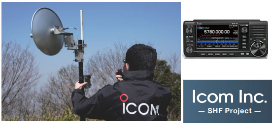
Back in the first half of 2022, I was following the progress of what was termed the 'ICOM SHF Project'. ICOM first announced this in December of 2021 and it suggested that they were developing a transceiver for the 2.4 GHz and 5.6 GHz microwave bands. See my earlier post HERE.
The blog post got a good deal of traffic and it was obvious that a lot of people were interested in this product even if was supposed to be for only two microwave bands.
I don't think many people had an idea earlier in the year just what ICOM had in the pipeline and it turned out to be pretty amazing.
In this post, I'll look at the new IC-905 in two parts. The first part is a summary and if anyone wants to look at the finer detail, that will be in the second half of this post further down.
In a future post, I'll look at the 10 GHz system.
Part 1 - The ICOM IC-905 in summary
The ICOM IC-905
At the Tokyo Hamfair in August of 2022, ICOM announced their new IC-905 radio which covers the following bands... 144 MHz (2m) 432 MHz (70cms) 1296 MHz (23cms) 2.4 GHz (13cms) 5.6 GHz (6cms)
They also have an optional transverter for 10 GHz (3cms).
As you can see from the photo above, it does have a similar appearance to the current IC-705 model which covers all of the HF, 6m, 2m & 70cms bands.
Note however that there is no RF in this part of the IC-905, it's just the control unit. The radio itself or at least the RF part of it is in the head unit which goes up next to the antenna.
This is part of the concept of putting the control unit indoors where the user is and putting the radio (RF) section up at the antenna. The 'LAN Cable' connecting the two will use PoE (Power over Ethernet) which will carry power and control signals up to the RF module as well as transferring the signals from the radio back down to the controller.
The main point here is to eliminate losses from coaxial cables running from the radio shack to the antenna. These can be really high at UHF and Microwave frequencies.
Some features of the IC-905 system...
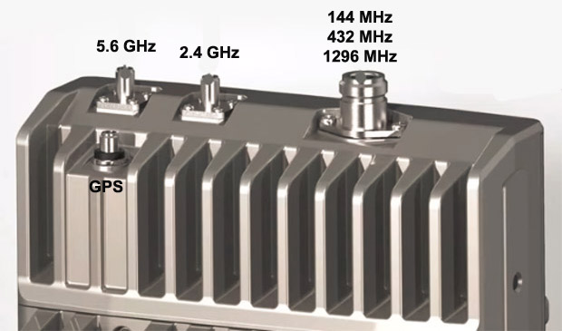
1) The power output is 10-watts on 144 MHz, 432 MHz and 1296 MHz from a single N-Type connector. There is a separate SMA type connector for 2.4 GHz and 5.6 GHz and the power on those bands is 2-watts.
2) The controller has a 4.3 inch (11cm) colour display and as you might expect, a real time spectrum scope and waterfall display.
3) All the usual analogue modes like FM, SSB & CW as well as the D-Star digital mode which is standard for an ICOM radio.
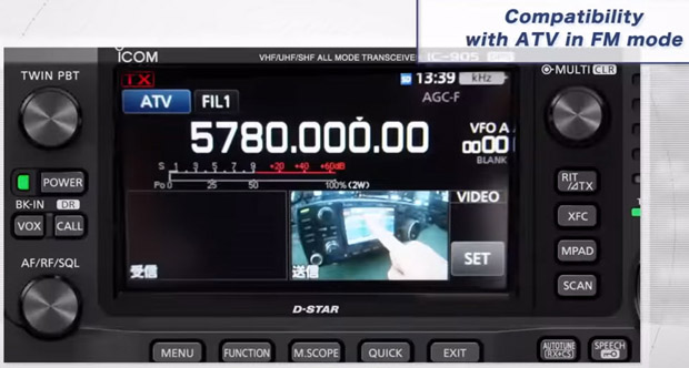
4) One nice feature is ATV (Amateur TV) in FM mode.
5) One feature of huge importance is that the RF module will be frequency locked by GPS. This is a major shortcoming in several of the existing ICOM rigs on the market in that frequency drift on some digital modes on the UHF bands is a major problem. The GPS locking should help resolve this.
Price & Availability...
As of November 2022, ICOM have not announced a price for the IC-905. I suspect it will be in the $2000-$2800 price range but we'll have to wait and see.
As for availability, they haven't announced it. I suspect it will be the second half of 2023 before we see any units for sale.
Game Changer...
When ICOM released their IC-705 radio, there was huge interest in it despite it being a low power 10-watt radio. One of the key selling points is that it was a 'shack in a box' with all of the bands from 1.8 MHz to 432 MHz in one unit.
In a similar vein, the new IC-905 is very much a 'shack in a box' for the VHF bands and above. If ICOM had announced a new VHF/UHF radio with just 144 MHz, 432 MHz & 1296 MHz, there would be a lot of interest in it. The fact the IC-905 has 2.4 GHz and 5.6 GHz as well is pretty amazing.
I suspect the biggest change will be to the 1296 MHz or 23cms band. There is a serious lack of radios available for this microwave band and getting a separate radio for just one band is prohibitive.
Close up of the base of the Diamond X6000A
I can see a LOT of people buying Tri-Band type verticals made by the like of Diamond and Comet and using them with the new IC-905. I think it's going to generate a lot of activity on the 23cms band in urban areas in many parts of the world.
The thing about a radio like this is that it is really versatile. People may come up with new ways of using it that we haven't considered at the moment.
I can really see this radio being a game changer for the UHF and low microwave bands IF the price isn't too high.
***
Part 2 - The ICOM IC-905 in more detail
IC-905 Controller... Let's have a look at this is a bit more detail.
The image above shows the front of the IC-905 and you get some idea of the depth as well.
The photo above is of the front of the controller from the Toyko Hamfair last August.
The photo above shows the rear of the controller and again, you get some idea of the depth.
As you can see from the photo above, there is very little on the rear of the controller other than two heatsinks.
While the IC-905 uses a 12-volt supply, it seems likely that there is a much higher voltage going up the Power over Ethernet cable to the RF unit. It's likely that there is some type of switch mode power supply in the controller to generate this higher voltage and a reasonable heatsink is required for that. There are of course all of the low voltage supplies to all of the electronics in the controller as well and again, a heat sink aids in keeping things cool.
The image above shows the right hand side of the controller.
The image above shows the right hand side in more detail. The port with the Green LED and the cable in it is the Power over Ethernet cable that goes to the RF module.
The image above shows the left side of the controller with the various ports.
The photo above is an actual photo of the left side of the controller.
And now onto the RF module. This image above gives an overview of the underside of the RF module. From left to right...
a) The cable on the left is Power over Ethernet LAN cable from the controller unit.
b) The BNC socket has an RF output at 10 MHz which is controlled by a GPS unit inside the RF module. The 10 MHz signal reference from here is fed to the optional 10-GHz transverter and provides that unit with a stable frequency reference.
c) The connector on the right is for the CX-10G which is the optional 10 GHz transverter.
This image above is another view of the underside of the RF module.
The image above is the top side of the RF module. All 2m, 70cms & 23cms signals are fed out via one N-type socket. Both the 2.4 GHz and 5.6 GHz bands have their own individual SMA socket. There is also a SMA socket for a small whip antenna for to receive GPS signals.
The image above gives another view of the top side of the RF module.
The image above shows the top side with the GPS antenna connected.
The image above is an actual photo of the RF module on display at the Tokyo Hamfair.
If we consider that a N-type connector is about 2cms in diameter then the dimensions of the RF module above is about 18cms across and 26cms in height. The depth is perhaps in the region of 8cms.
In terms of operation, the new IC-905 is basically the same as the popular IC-705.
This image above is a screenshot from the controller showing it operating on the 5.6 GHz band with a selection of modes.
The image above is a screenshot of the 11cm display showing a selection of menu items.
One amazing feature of this radio is it's ability to use ATV (Amateur TeleVision). In the above image, you can see a received ATV signal inset in the screen.
And this is the received signal on full screen.
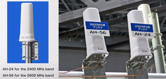
ICOM also intend to sell omni-directional antennas for both the 2.4 GHz and 5.6 GHz bands.
I suspect third party antennas for these bands will be a lot cheaper.
Video... and finally, this is the promotional video from ICOM for the IC-905
That's it. I've done my best to collate all of the information available and put it in one spot. We'll just have to wait now until ICOM announce a release date and price.
Addendum 25th Dec 2022... At a recent presentation, ICOM had this slide which showed the frequency stability of the new IC-905 versus the old IC-9700.
The IC-9700 which was released in 2019 and is a VHF/UHF transceiver covering 2m, 70cms and 23cms. It is not frequency disciplined by an external source and as can be seen from the chart on the left, it can drift hundreds of Hz with a change in temperature on the 23cms band.
This isn't an issue on say FM, D-Star, SSB or CW but it is on the very weak signal modes like FT8 or WSPR where a high level of frequency stability is required. This has led to some third party providers providing frequency stability solutions.
The chart on the right by contrast is that of the IC-905 at roughly four times the RF frequency. The IC-905 which is frequency stabilised by GPS only drifts a few Hz with changes in temperature.
This really is a game changer for all the VHF, UHF and SHF bands as frequency stability is now essential for very weal signal modes.
I came across details of this QSO recently which I thought was interesting. While long distance contacts in the region of 700kms on the 70cms UHF band are probably not that unusual in the Caribbean, this one was of interest as it was via D-STAR, a digital voice mode.
On the 18th of April 2021, Brett PJ2BR on Curacao completed a successful contact with Jose WP4KJJ on Puerto Rico on 432 MHz using D-STAR. See video below.
It's very easy to find videos or information about D-STAR being used for working through local digital repeaters or local contacts but it's unusual to see it being used for a long distance contact on the 70cms UHF band.
When you think you’ve done it all...Opening on 70cm to Puerto Rico. @WP4KJJ and I had a short DV/Dstar QSO on 70cm!! I am ecstatic! Distance 736Km, DV. Breaks the Covid lockdown routine 😁 One for the books. pic.twitter.com/iEVKESi2Re
If you're interested in the upper HF bands or any of the VHF and UHF bands then your horizon is all important. On bands like 144 MHz and above, the vast majority of signals are coming in from the horizon and just above it.
On bands like 28 MHz, 50 MHz & 70 MHz, the signals may be coming in at a slightly higher angle with Sporadic-E but they are still very close to the horizon. Whether you're operating from home or thinking or going portable then knowing your horizon can help explain what's going on.
In this post, we'll look at how to use it and some tips on getting them most out of it. To help explain it, I am going to do a profile of Paul Logan's location in Lisnaskea in Co.Fermanagh, Ireland. Paul is an avid listener to the Band 2 FM band from 88 to 108 MHz and logs hundreds of radio stations from all over Europe every year.
Getting started...
After going to the HeyWhatsThat site, click on the 'New panorama', zoom in to find your own location on the map and then click on it.
I have done this in the example above for Paul's location and them zoomed back out. On the left side of the screen, your latitude and longitude will be automatically filled in after you click on the map. You can also select the height above ground so I selected 8-metres which is the height of Paul's antenna.
Note that the site uses the general topography to calculate your horizon, it doesn't take buildings or trees into account.
Also make sure to select 'Metric' at the bottom of the screen to use proper measurements.
Then click 'Submit request'.
Using the results...
After a short while, a map is generated. I clicked on the 'Visibility cloak' to show the areas that are visible from Paul's location. The Red triangles are distant peaks and I clicked on 'Contours' to highlight the topography.
This is that the horizon looks like for Paul...
I have exaggerated the vertical scale and added some numbers to make it clearer.
There is a large hill with an elevation of about 5 degrees to the north-east of Paul's location (45 deg bearing) and this is clearly shown on the image above. This would have a major impact on all signals at 144 MHz and above. As Paul notes himself, he finds it very difficult to get distant stations on Band 2 in that direction.
That hill would also impact on all long distance single hop Sporadic-E coming from that direction on all bands from 28 MHz to 144 MHz. Short skip arriving at a higher angles on say 28 MHz or 50 MHz would probably clear the hill.
Due east at 90 degrees, there is an interesting gap which might might allow some distant Band 2 tropo or Sporadic-E through.
From 100 to 140 is another impediment to low angle signals but it gets much better after 150 degrees or so. Paul has a very good take off at about 190 degrees towards the Canary Islands and even those distant line of sight peaks around 270 degrees are so low that there are unlikely to be much of a problem. As a result, his location will be wide open to say the USA on 28 MHz once the sunspot numbers increase.
Example 1: Poor tropo path to Scotland.
In this example, I have shown what the path is like to Scotland and how the hill is in the way. If you are trying this from your location, then just click on any location of interest and the site will show you the path and where it is on your horizon.
Example 2: Good tropo path to Spain
As can be seen from the horizon profile, Paul has a good path to the south and this can allow him to gain access to the marine duct that sometimes occurs between Ireland and Spain. The distance shown is about 1200kms which is really good for Band 2 tropo.
Example 3: Sporadic-E footprints...
Using the 'Up in the air' button, I was able to simulate what the limit for one hop Sporadic-E from Paul's location might be. One the left above is the approximate range if Paul had a completely flat horizon. The one on the right is the reality.
For Italy, the local hill restricts signals further south than Rome.
For Poland, signals from the east of the country should be easy to hear except the local hill makes things more difficult. Belarus and the west of Ukraine are also more difficult. Notice that that little gap at 90 degrees is reflected in the Sporadic-E footprint.
For the Baltic states and Finland, they should be well within Sporadic-E range but again, the local hill makes things difficult.
It's possible in many cases that some local tropo conditions will extend the footprint further east but overall, the local hills make hearing these areas more challenging.
Example 4: F2 propagation...
As the sunspots increase, there will be weak F2 openings on 28 MHz. Towards the west, Paul should have no problems reaching Newfoundland and Nova Scotia in Canada. With the help of a more southerly second hop, he is well placed to hear signals from well into the USA.
Towards the eastern Mediterranean, the local hill will block some of those signals when the band is just open. Ironically, it may actually be easier to hear signals further away in places like the Arabian peninsula once there is a second hop.
'Up in the air' Values...
For your own propagation footprint maps, try 360000 for Sporadic-E and 1300000 for F2.
Example 5: Line of sight paths...
The HeyWhatsThat site can also be used to examine line of site paths. The map above shows the path from Paul's location to Clermont Carn in Co.Louth, about 75kms away. This is a major transmitter site for Irish radio stations.
Let's say for example, Paul wanted to get a line of sight path for a contact on the microwave bands. The profile below shows the local hill in the way but there is a location 7kms away that is line of sight to Clermont Carn.
It's not hard to imagine how it might be used for finding suitable paths on the microwave bands or even if someone was just curious if a distant mountain was visible or not.
Other uses... Here's a few...
Portable operation, DX-peditions, Summits on the Air (SOTA) activations, contesting ... are there obstructions in the way? Is your 'perfect' contest location blocked at a low angle on the upper HF bands say to the USA?
In summary... This is a very useful utility to have and the more you use it, you tend to think of other uses.
For the bands like 28 MHz and 50 MHz, short skip can hide the shortcomings you may have in a certain directions. Your horizon profile should make you aware of these and you're looking for no more than 2 degrees.
For the higher bands like 70 MHz, 88 to 108 MHz, 144 MHz and above, tropo becomes a more important propagation mode. This time, you're looking for a very low horizon and the lower the better.
There's a very good reason why people put antennas up as high as possible on the VHF and UHF bands.